Cadia Girth Gear Failures
SUMMARY
This is an update of work presented at the SAG 2001 conference on the Cadia gears [1]. Both gears and pinions on twin ball mills failed almost simultaneously. Our 2001 paper showed that the location of the failures is explained by the shape of the girth gear blanks. Fresko et. al. [2] shows that T-gears are in fact better than Y-gears in terms of load distribution and that the diameter of the pinion in a gear set can result in excessively high loads at the ends of the pinions. A more refined analysis of the Cadia gear sets performed by EAnD in 2006/7 shows that the load on the Cadia gears was very poorly distributed and this poor load distribution is even worse than that estimated in [2]. The location of the failures at Cadia can only be explained by thermal ratcheting. Regardless of the differences in all work done, the conclusion is the same, the Cadia gear set failed due to design and not anything to do with operation of the mills, i.e., lubrication choices.
DISCUSSION
In 2001, we published a paper [1] that showed that the scoring of the Cadia girth gears was related to the thermal ratcheting of the gear set. In summary, the analysis showed that the non-uniform shape of the girth gear resulted in differential thermal expansion, i.e., more expansion on one side of the gear vs the other. This expansion explained why one of the girth gears at Cadia failed at the drive end and the other failed at the non-drive end. The expansion is shown in Figure 1. The work in [1] was limited by the size of the model we were able to create to simulate the failure.
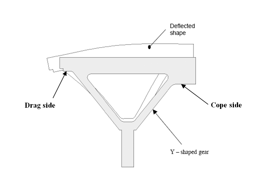 Figure 1: Differential expansion in a girth gear
In 2004, Fresko et. al. [2] presented a paper that showed that a T-shaped gear resulted in a load distribution across the tooth that was about 7% more uniform than the “Y-shaped” gear in Figure 1. This paper presented a more advanced model of gear sets than that used in [1] in that both the pinion and the gear were modelled together to estimate the load on the tooth flanks. The limitation of the paper is shown in Figure 2. Whilst the helix of the teeth was modelled, the contact was idealised as acting along the pitch line of the gear face simultaneously and only one tooth was in contact. This is effectively considering the gear and pinions as being spur gears but still, this is an improvement over the model in [1].
The gear tooth loading profiles for T and Y-shaped gears obtained in [2] are shown in Figure 3. Interestingly, the “alignment” of the pinion for the T-gear seems to have been chosen so that it results in a misaligned pinion over the rib thereby resulting in a higher peak load at the non-drive end of the pinion. This is an odd choice if the T and Y-gears are to be compared equally but nevertheless, the load factor for the T-gear is 7% (1.91 vs 2.04) better then the Y-gear. It is clear that this could improved by a further 5% if the pinion were “aligned” over the rib rather than over the window.
A further conclusion from [2] is that the pinion diameter is more important that gear blank profile (Y or T). So, according to [2], the failure of those gears was caused by a design fault, i.e., the diameter of the pinions in the Cadia ball mills are too small.
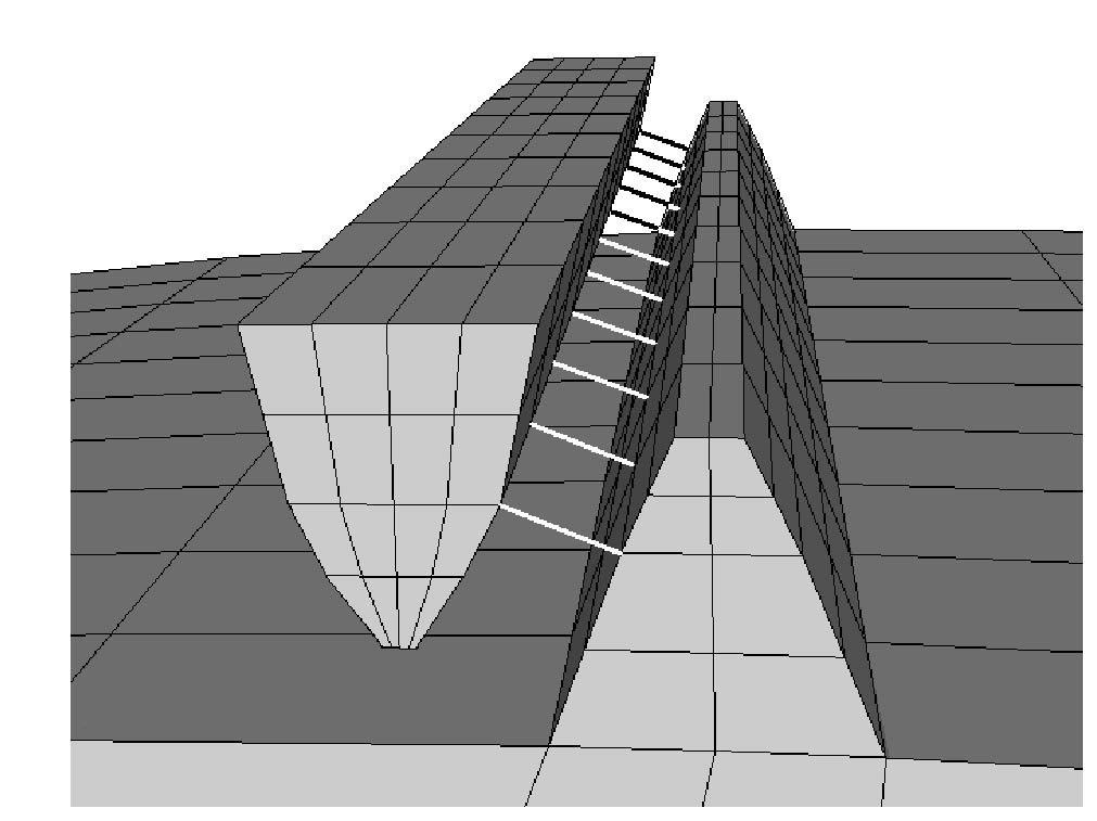 Figure 2: Model of gear contact in [2] – similar to a spur gear, not a helical gear
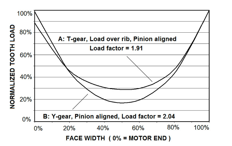 Figure 3: Load distribution from [2] for T and Y shaped gears
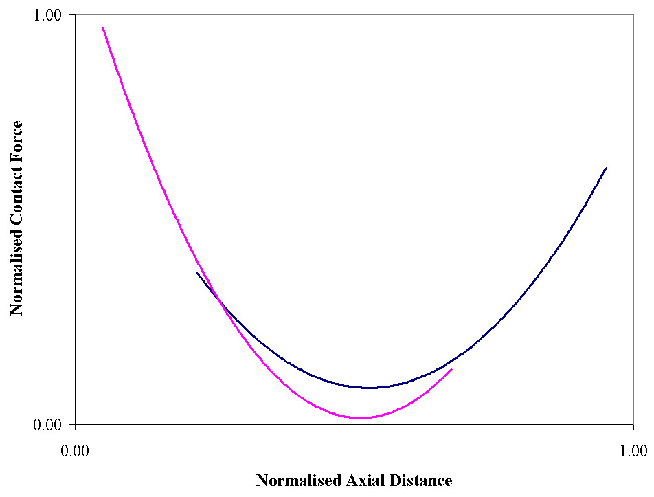
In 2006, we undertook a further analysis of the Cadia gear set because PCs had reached a level that allowed detailed modelling of the gear, the pinion and the actual tooth contact line. The model of the gears is shown in Figure 4(a) and the typical calculated contact pattern for both of the Cadia gears (there are two mills at Cadia) is shown in Figure 4(b). Note the following:
- There is more than one load line in the load plot because there is more than one tooth in contact.
- The tooth contact line was determined by the intersection of the two involutes of the mating teeth, i.e., the contact occurs along a line that is inclined to the pitch line.
- There is almost no load taken at the centre of the gears due to the relative stiffness of the mating gears. This load variation is much greater than that obtained using the approximate methods in [2] for a Y gear.
The contact load patter in Figure 4(b) implies that the Cadia gears should have both failed at the drive end of the pinions. However, they did not. One failed at the drive end and the other failed at the non-drive end. The only explanation for this given the alignment process that was undertaken prior to the failure is that the Y gear expanded preferentially at the cope end and that the cope ends of the gears match the locations of the scoring. Indeed, adding heat to the gear simulates this effect.
The damage to the girth gear was on both the loaded and unloaded flanks. Site inspections (see Figure 5) concluded that the backlash had been entirely taken up by the relative expansion of the gear to the pinion. This is consistent with thermal ratcheting.
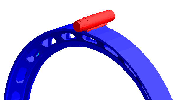
(a) Gear and pinion model for Cadia gears
 (b) Typical load distribution on Cadia gear teeth
Figure 4: Model of Cadia gears with correct contact and resultant load distribution
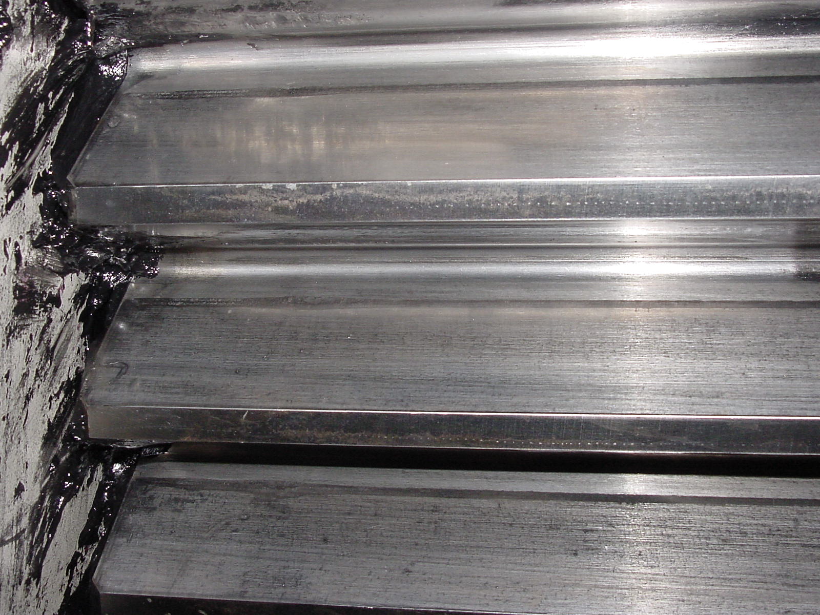 Figure 5: Damage to girth gear
(Note: The damage to the loaded flank can be seen on the under-side of the top tooth; the damage to the unloaded flank can be seen on the top sides of the three lower teeth.)
CONCLUSION
The gears and pinions on the Cadia ball mill gears failed due to a design fault. We agree with [2] that a larger pinion may have avoided the gear scoring, however, the location of the damage can only be explained by thermal ratcheting resulting in differential expansion. The damage to both the loaded and unloaded flanks of the girth gear are consistent with the gears almost jamming.
References:
[1] Meimaris, C., Duncan, M. D., Cox, L., 2001. Failure analysis of ball mill gears, SAG 2001 Conference, Vancouver.
[2] Fresko et. al. 2004. The use of finite element analysis in the understanding of alignment and load distribution in large grinding mill gear and pinion sets. SME Annual Meeting, Denver, CO.