Shell vs Trunnion-Mounted Mills
There is substantial open literature regarding the structural and mechanical design of large grinding mills. In most cases, published work is in the form of conference papers and mining society journals. It is unclear how many of these papers were peer reviewed prior to publication. There are a number of recurring themes and conflicts in the vendor publications relating to the relative benefits of shell and trunnion-mounted mills, namely:
- Shell-mounted mills are not as reliable as trunnion-mounted mills because they rely on a T-welds that connect the end-plate to riding-ring (journal) (Svalbonas, [1, 2]).
- Trunnion-mounted mills are not as reliable as shell-mounted mills because they rely on large castings that are often found to have unacceptable flaws according to Knecht [3] and Leonard [4].
- Shell-mounted mills are not as stiff as trunnion-mounted mills according to Svalbonas [1, 2].
- Trunnion-mounted mills are not as stiff as shell-mounted mills according to Knecht [3] and Leonard [4].
It is evident that the claims of Svalbonas and those of Knecht and Leonard cannot both be correct.
The main problem with vendor publications regarding the choice between shell and trunnion-mounted mills is the potential for bias. Vendors often promote the benefits of their own design by directly contradicting the claims of the other vendors. For example, when Leonard was employed by Nordberg who built shell-mounted mills, he declared in [4] that shell-mounted mills represented a “revolution” in mill design that would “increasingly become the standard arrangement for large mills”. He justified his claim on the basis that shell-mounted mills did not require large castings that could delay project completion due to the presence of casting flaws; that they have greater stiffness that results in a “superior load distribution”, less maintenance downtime for gear alignment, and lower bending moments in the shell; and that they require smaller foundations without high piers and that this gives greater flexibility in drive arrangements. However, when he joined Metso in 2001 as its President, he did not transport the shell-mounted mill revolution. Metso continued to make trunnion-mounted mills. He did not eliminate castings from Metso mills and the stiffness of the Metso mills was not increased to improve load distribution or gear alignment. In fact, Svalbonas who was the Director of Engineering at Metso under Leonard states in [1] that the “much heralded elimination of castings [in [4]] actually lowers the overall safety of the mill structure” in shell-mounted mills. Svalbonas directly contradicts Leonard’s claim of higher stiffness in shell-mounted mills stating that both Leonard and Knecht [3] are wrong because they use simple beam theory to reach their conclusions on stiffness. Svalbonas raises several other potential difficulties in the design of shell-mounted mills in [1]:
- It is more difficult to effectively seal the lubrication oil for the main support bearings in shell-mounted mills due to their large journal diameters;
- The allowable stress ranges for welds in shell-mounted mills should be less than those in trunnion-mounted mills because the T-joint at the bearings has internal weld surfaces that may be exposed to the mill contents;
- In segmented shell-mounted mills of the type built by Polysius, there is an unbolted section of the journal between the centre of the T-joint and the start of the inboard axial flange and this could open under load.
- Shell-mounted mill designs have not been subjected to “analytic scrutiny and strain gauge study” to the extent that trunnion-mounted mills have been.
In the following sections, we will show that the disadvantages attributed to shell-mounted mills by trunnion-mounted mill manufacturers are either exaggerated or incorrect and that both mill types can be designed with the same or similar levels of safety.
1 – Stiffness
There is no particular problem with stiffness in grinding mills. Both mill types can be made sufficiently stiff. The issue appears to be a case of highlighting an attribute of a particular mill type that has no practical significance to the mill installation. Shell-mounted mills with end walls directly above the main bearings are generally stiffer than trunnion-mounted mills. We have checked this by comparing a 26 ft shell-mounted ball mill with a trunnion-mounted mill of equal grinding volume and same diameter. Detailed finite element models of each mill were created. The number of nodes and elements in each model differ by less than 5%. The elements used in the finite element mesh are parabolic with mid-side nodes. Each mesh has four elements through the thickness of the shells and heads and the maximum element aspect ratio is less than 1.5. These are much more detailed models than any vendor uses in mill designs. The same liner and charge loads is used in both models. The calculated overall stiffness for the shell mounted mill is 10.8 GN/m and 8.6 GN/m for the trunnion-mounted mill. Both of these stiffnesses are very large. Both are sufficient to enable proper operation of both gear and gearless drives. The stiffness argument is a distraction brought about by the competitiveness of mill vendors. It should be considered a peripheral issue when assessing mill types.
One stiffness related matter that is more important than the overall stiffness of mills is the local stiffness of the bearing surface. Svalbonas [4] argues that their trunnions are stiffer than the bearing surface of shell-mounted mills. This is incorrect when applied to the standard shell-mounted mill built by Polysius, Outotec and FFE (in the past). These shell-mounted mills have an end-wall welded to the journal that stiffens the journal immensely. For the 26 ft mills in the previous paragraph, the maximum local deflection of the journal over a bearing pad is 100 times less in the shell-mounted mill than it is in the trunnion-mounted mill, i.e., the journal is 100 times stiffer in the shell-mounted mill.
So, shell-mounted mills with end plates directly above the bearings are stiffer than trunnion-mounted mills but both are stiff enough.
2 – The elimination of castings increases the risk in shell-mounted mills: Svalbonas [1]
Svalbonas’ argument is based on the premise that welded joints have lower safety factors than castings and since there are no castings in shell-mounted mills, they should represent more risk. This is incorrect since both mill types have welded joints and the internal surfaces of these welds can be exposed to the mill contents. If a volume basis of risk is used, then superficially, Svalbonas’ claim may be right (by weighting the lower risk castings and higher risk shells) provided we accept Svalbonas’ claim that castings have a safety factor of ~2 vs 1.3 for welds. However, trunnion-mounted mill vendors in North America neglect local stress concentrations in heads at the ends of split flanges and so the safety factor of 2 for castings claimed by Svalbonas is excessive. Weldments and castings will have similar factors of safety at the highest stress locations in a component. Furthermore, the observation that iron castings result in delays due to the presence of casting flaws in [4] is valid as experienced on many projects.
The arguments for or against the use of castings in mills are not a strong reason to favour or reject shell-mounted mills. This is supported by Svalbonas’ observation that the welds in both shell and trunnion-mounted mill types can be designed to the same level of risk [1].
3 – Effective sealing of the bearing surface
The larger the bearing surface (journal) the harder it is to seal. Our discussions with operators of large shell-mounted ball mills indicate that whilst the bearing seals leak, they do not a substantial maintenance problem. This may or may not be the case for larger diameter mills but the best people to contact regarding this issue are site maintenance personnel, not trunnion-mounted mill vendors. This issue is not a critical in terms of mill structural integrity.
4 – Risk from internal welds at T-joint
In [1], Svalbonas equates the internal weld at the T-joint with the internal corner welds in older trunnion-mounted mills. These older mills failed prematurely more frequently than modern mills have (those with out-turned flanges). Svalbonas states that allowable stress ranges at internal weld surfaces of the T-joints must be lower than they are for external welds because they are they are subjected to corrosion, erosion, accidental damage and have a different ratio of tensile to compressive stresses than external welds. There are two problems with this argument, namely:
- Modern trunnion-mounted mills also have welds with “internal” surfaces that are relatively highly stressed at the head to shell flanges and these surfaces can be subjected to corrosion, erosion and accidental damage as easily as T-joint welds internal in shell-mounted mills.
- The comparison of the welds at T-joints made in European facilities today with those of older trunnion-mounted mills is inappropriate. The current best-practice for T-joints welds is that they are machined to a radius that is flush to adjoining parent plate surfaces (and below any toe defects). This results in much lower toe and peak stress ranges in the weld compared with the welds in many of the older trunnion-mounted mills that were only toe ground or not ground at all. The welding processes, consumables and parent metals used in these T-joints are of much higher quality than those used in older trunnion-mounted mills and the joints also undergo more stringent inspections than the older mills did. Times move on and technology improves.
Svalbonas does pull back from this comparison when he states later that both shell and trunnion-mounted mills can be engineered to have the same level of risk. This has been proven recently. The largest shell-mounted ball mills in the world are designed to stress ranges that are less than the allowable stress ranges for internal welds used by both of the US trunnion-mounted mill manufacturers.
What if the mills are segmented axially to facilitate transportation? We have undertaken detailed finite element analyses of axially split shell and trunnion-mounted mills. The increase in stress range at the T joint welds in shell-mounted mills is the same as the increase in stress range at internal welds caused by the segmentation in trunnion-mounted mills.
It can be concluded that shell-mounted and trunnion-mounted mills can be designed with the same safety factors for internal welds for both segmented and unsegmented mills.
5 – Structural Effects of Segmentation
Segmentation of shell-mounted mills is discussed by Svalbonas in [1, 2, 6]. Some options available for segmentation are shown in Figure 1.
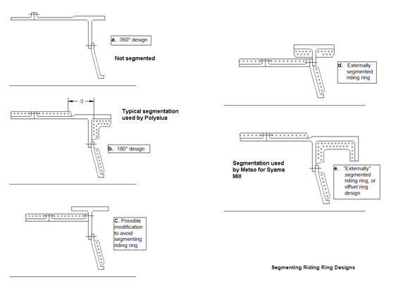 Fig. 1. Options for segmentation of riding rings – reproduced from [1] – SAG 2001 Conference, Vancouver
The world’s largest manufacturer of shell-mounted mills, Polysius, uses configurations in Figure 1(a) and (b) with the additional option of site welding to eliminate the circumferential bolted flanges at the can-to-can joint that are shown in Figure 1 (a). There is no structural disadvantage in the design of a shell-mounted mill of the type shown in Figure 1(a) when compared with a similar sized trunnion-mounted mill. In fact, the use of site welding of the shell sections favoured by Polysius is advantageous as bolt failures in flanged mills can lead to structural failures such as those that have occurred recently in South America.
The unclamped length ‘a’ in Figure 1(b) is considered in [1] to require “some extreme designing [that] has not been demonstrated so far” to ensure trouble-free operation that prevents contamination of the bearing. The Ernest Henry SAG mill has this design and although it has suffered contamination of the bearing oil by mill slurry, it has operated continuously since 1997 without a structural failure. The sealing of this region has been improved by a number of pressure grooves and barriers being added to the joint in newer mills. Initial feedback from Hidden Valley (Newcrest), which also has a segmented shell-supported SAG mill, indicates that there are no operational or maintenance issues related to the riding ring (journal) split.
6 – Site welding
Trunnion-mounted mill vendors in their tenders and presentations state that bolting sections together is preferable to site welding because full stress-relieving cannot be completed in the field and the presence of localised residual stresses after site welding require that the shell-mounted mill must be designed using heavier sections. This description of the effects of site welding is an exaggeration. In [6], Svalbonas writes that “site welding of components … is acceptable as long as it is realised that this is not just an alternative erection procedure but it is actually a design change”. He goes on to raise residual stresses but when seen in the context of the quoted sentence, it is seen that there is no fundamental problem with site welding.
The ball mills at Cerro Verde rely on site welding. The calculated stress ranges for a design load of 45% total charge with 40% ball charge were no greater than 30 MPa at the location of the site welds. The stress ranges conform to all established design codes for weld fatigue such as BS7608. Both Svalbonas [5, 7] and Farnell-Thompson/FLS [8] consider BS7608 to be too conservative (stringent) for trunnion-mounted mill design as it requires a reduction of the allowable stress range as a function of plate thickness, so site welded joints are not a great risk if designed properly.
Site welding is a viable alternative to bolted joints.
7 – Validation of shell-mounted mill designs: Stress relief and Strain Gauging
We are aware that mill design consultants claim that post-weld heat treatment of welded joints in shell-mounted mills is not as effective as it is in trunnion-mounted mills. This statement is incorrect. Residual stress measurements performed on the Pueblo Viejo project using strain gauges mounted on and adjacent to the T joint welds. These measurements showed that that the level of stress relief achieved at a the T-joint after post-weld-heat-treatment is as much as would be expected in the end flanges of trunnion-mounted mills.
Strain gauging of shell-mounted mills has been undertaken in the past. Some results have been published in SAG mill conferences. Strain gauges were also used to check the design of the CMDIC shell-mounted ball mills. The statement in [1] that shell mounted mills have not been thoroughly tested is incorrect.
CONCLUSION
Shell-mounted mills can be designed to same level of safety (risk) as trunnion-mounted mills. Shell-mounted mills with end walls directly over the main bearings are stiffer than trunnion-mounted mills both globally and locally (at the bearing journals) but this is not a parameter that should influence a mill purchase as both mill types are sufficiently stiff. The segmentation of shell-mounted mills can be designed so that the adjacent welds are not over-stressed. The axial split in the riding ring (journal) that is not clamped, Figure 1(b), presents a potential design issue that requires attention to detail by the mill designer but we are not aware of any failures emanating from this region. The sealing of this region has been improved substantially over the past 15 years. Site welding should not be considered as a poor design choice. The choice of site welding or bolted flanges should be based on a number of factors such as previous vendor experience, expert personnel availability, construction schedule and planning, future maintenance advantages and disadvantages, and stress range rather than the irrelevant fact these these welds will not stress relieved.
Trunnion-mounted mills have been shown to be reliable provided detailing is properly considered. Thickness of flanges, the use of contour flanges versus plate flanges, bolting design and segmentation should all be considered during a tender review. This is particularly the case when North American vendors and design consultants are chosen as they do not model three-dimensional details such as head and shell-axial flanges.
Trunnion-mounted mills are not inherently “better” than shell-mounted mills and vice versa.
REFERENCES
[1] Svalbonas, V., 2001. Difficulties in mill comparisons – Shell supported vs trunnion.In: Barratt et al. (Eds.), Proceedings International Autogenous and Semiautogenous Grinding Technology 2001.
[2] Svalbonas, V., 2002. The design of grinding mills, in Mineral Processing Plant Design, Practice and Control: Proceedings Vol 1: ed. A. L. Mular, D. N. Ialbe, D. J. Barratt, SME
[3] Knecht, J. ; Tew, A. 1999. World’s Largest Shell Supported SAG Mill At The Ernest Henry Concentrator-Operating Experiences And Results. SME Annual Meeting, Denver, Colorado.
[4] Leonard, J., 1999. Evolution to revolution. (third generation shell supported mining mills). Mining Magazine, April.
[5] Svalbonas, V., Berney-Fiklin, J., 2006. History of weld design for grinding mills (a participant’s view). In: Barratt et al. (Eds.), Proceedings International Autogenous and Semiautogenous Grinding Technology 2006.
[6] Svalbonas, V., 1999, Mechanical design of large grinding mills – AG/SAG Part 1, prepared for Mineral processing and hydrometallurgical plant design – World’s best practice, Australia Mineral Foundation.
[7] Svalbonas, V., Fresko, M., 2002. How safe are your recent mills?: The compatibility between FEA and welding codes. SME Annual Meeting, Phoenix, Arizona.
[8] Farnell-Thompson Applied Technologies & FLS: From tender negotiations and design reviews on several projects.