Literature Review: Gearless Motor Failures – A Mill Designer’s Viewpoint
In [1], Svalbonas reviews the states-of-the-art in the design of grinding mills and ring-motors (for gearless drives). He concludes that failures in ring motors occurred because the structural design of these motors had not been validated through measurement. Svalbonas expresses his hope that gearless drive manufacturers will follow the example of mill designers who used structural reinforcements, increased radii and finally finite element analysis (FEA) coupled with strain gauge measurement of mill structures to avoid failures. He states that motors should be instrumented to obtain data for both “nominal” and “perturbed” conditions to get a “more accurate understanding of the local stresses and their variability” and concludes that this is the only way that the “real safety factors on design [can] be determined”. Svalbonas believes that the failures in ring motors are not “directly diameter oriented”. He says that the failures “could have just as easily appeared” on other ring motors, i.e., any smaller motors. This is at odds with the observation that the specific failures discussed in [1] have not been observed in small diameter machines such as those used to drive ball mills.
Svalbonas’ paper paints the state-of-the-art in ring motor design as being in a parlous and undeveloped state in comparison with that of mills. Is this is reasonable depiction of the two machines? The answer is “No”. We have recently undertaken failure analyses of six mills built using all the modern design methods described [1], so mills still do fail. The structural analysis of some of the largest mills in the world is primitive when compared with the design technology available in general industry today. There is no uniformity in design approaches between any of the mill vendors. Metso, FLS and Outotec mills are designed using different detailing and allowable stress ranges for welds and there are major differences in the way these companies assess the structural integrity of SG iron castings. Furthermore, the design verification of mills by strain gauging has not always been performed properly as in [2] and elsewhere, yet reliance on this strain gauging is the cornerstone of Svalbonas’ viewpoint on ring motor validation.
1 – Ring Motor and Mill Complexities
We have been fortunate to undertake detailed mechanical and structural design reviews and audits of all mill types from the five major mill vendors and of ring motors from both the gearless drive vendors. We have also been hired by mine owners to determine the causes of most of the major modern mill and ring motor failures that have occurred since 1998. This gives us a unique advantage in comparing the state-of-the-art in design for mills and ring motors. No mill or motor vendor, mill design company or independent consultant can truthfully claim this advantage. So let’s look at the observations in Svalbonas’ paper on gearless drives in [1].
The structural design of mills is much simpler than the structural design of ring motors. Most of the complexity in a mill is related to bearing design. However, Svalbonas restricts himself to structural design in his comparison of mills and ring motors in [1]. The rotating element (the shell, heads and trunnions) of a mill is a slowly rotating tube. Its structural design is often analysed using a simple, linear, two-dimensional finite element model and there is no need to undertake a dynamic analysis of the mill structure. A ring motor on the other hand is much more complex, be it an ABB or a Siemens design. The stiffness of a stator relies not only on its steel frame but also the core that the frame is designed to support. The core is not a homogeneous solid; it is a lamination of approximately 2000 sheets of steel, each about 0.5 mm thick and the stiffness of the lamination is dependent on the compression applied by lamination clamping bolts and plates. The attachment of the core to the frame is via one hundred or so keys that are either welded or wedged to hundreds of brackets. These brackets are welded to diaphragms in the frame and the diaphragms are welded to the three or five main rings of the frame. The completed frame cannot support the electromagnetic loads in the core by itself as it is not stiff enough. The final step in generating sufficient stiffness in the stator is achieved by the over-constraint in the supports of the frame on its foundations. The stator is fixed on both sides of the frame or at the bottom. There is no sliding at the foundation supports to prevent the generation of large thermal expansion loads in the frame and the foundation during operation. These thermal loads are only limited by the cooling system of the stator. A mill is much simpler. It is not over-constrained on its supports as it has fixed and floating bearings and there are no thermal loads to contend with. Even the rotor poles of a ring motor are more complex than a mill structure. They too are dependent on the steel laminations for stiffness and they are subject to highly non-linear forces as is the stator. The loading in a mill is simple in comparison as stated in [1].
The design task faced by the motor designer, even if limited as in [1] to “structural design” (which is clearly mechanical), is vastly more difficult than the task of the mill rotating element designer. There are more components to design. The stator and rotor components are subject to complex loading including non-linear electromagnetic loads in the air-gap and the thermal loads from the electrical losses. The electromagnetic loads generate high mean stresses in stator and rotor components as well as fatigue loading. The motor must be designed for accident conditions such as those produced by short circuits. These accident loads result in highly transient dynamic loads in which the rotor pull is released but the torque increases by roughly an order of magnitude. In contrast, mill vendors do not have to design for an accident condition (e.g., a dropped charge).
In summary, the rotating element of a mill is a simple structure that is intrinsically stiff and it is designed to accommodate well-defined cyclic loads that occur once per revolution. A ring motor is a complex machine that relies on its steel frames, the cores they support and the foundations (in the case of the stator frames) to achieve sufficient stiffness and is subject to static (thermal), cyclically dynamic and high-amplitude transient loads. Mills and motors are chalk and cheese in terms of complexity. This greater complexity of ring motors is considered only superficially in [1].
2 – The Failures Mentioned in [1]
It is interesting to consider the choices of subject in the paper and the way they are presented. We note that we were responsible for the failure analyses of all the failures related to ring motors mentioned in [1] and most of the design changes made to avoid these failures in subsequent motors. Svalbonas was not involved in these failure analyses nor has he contributed to the remedial designs or design changes to subsequent motors that arose therefrom. We also undertook a failure analysis of the KCGM mill and have analysed forged fabricated gears, both of which are mentioned in [1].
2.1 – KCGM mill and forged-fabricated gears
The review of the KCGM mill and mention of fabricated gears in [1] offer no benefit in the understanding of the ring motor failures or their design.
The cracks in the KCGM mill shell are primarily due to the installation of the mill. All the joints in the mill were lined up so that the head and shell joints all pried open resulting in very localised stress concentrations in the joints and eventually cracks in the welds. The comment in [1] that the “mill continues to run because we know that the local detail failure poses no immediate danger to the mill [due to] FEA studies and a history of mill strain-gaging instrumentation” is not true. The reason why we “know” that the mill has not failed is precisely because the mill has not failed. It is hindsight that tells us this, not strain gauging or FEA. Otherwise, the Owner would not have spent money investigating methods such as add-on brackets and doubler plates to ensure the cracks do not propagate.
In contrast to the cracks in the KCGM mill that seem dormant according to [1], consider the Candelaria SAG mill failure described by Yanez and Tapia in [3]. The SAG mill cracked through the flange and into the shell and this threatened the integrity of the mill. The crack repair required removal of balls and liners and half the head to enable access to the the crack. This was as substantial an undertaking as the repairs to the Cadia rotor poles and required more time to complete. Again, FEA and strain gauging were not necessary to assess the danger that the crack posed to the mill because it was sufficient to observe that the crack was growing. FEA and strain gauging in isolation do not make components “safe”; good overall design does.
The comparison of the details in the gussets in the Cadia rotor poles with the scalloped gussets in fabricated gears in [1] is misleading. The root cause of the rotor pole failures is unrelated to the shape of gussets. Furthermore, the loading of gears and rotor poles is completely different. There is no fundamental reason to believe that fabricated gears with gussets will result in premature failure.
2.2 – The Cadia rotor pole failure
EAnD were engaged by the mine owners to determine the technical (proximal) and root causes of the stator vibrations and the rotor pole failures in the Cadia motor by Newcrest Mining, the owner. In both cases, we undertook dynamic measurements of the equipment followed by complete finite element analyses of the ring motors to determine the causes of failure. The changes made to the motors were recommended by EAnD and these have been adopted by Siemens in the all their new motors. The reviews were published in various papers [4, 5, 6, 7]. The discussion we present on ring motors is based on facts and not supposition.
2.2.1 – History of the Siemens ring motor design
The failure of the welded ribs in the Siemens large diameter motors was first observed at Cadia. We measured the stress range at the toe of the weld using strain gauges as shown in Figure 1 and found that it was slightly greater than the allowable stress range in fatigue design codes. The strain measurements showed that stiffness of the rotor pole laminations was substantially less than the value used in the design. We found a similar result in the investigation of vibrations in the stator [7]. The proximal or direct cause of the rotor pole failures is an error in estimating material properties. It is not due the welding design, the use of gussets, attempts to avoid intersecting welds, weld accessibility, or welding stop-starts as stated in [1]. The choice in the repair of the poles to change the weld design from partial to full penetration welds and to grind the weld toes was made because it was more practical to upgrade the welds in a site repair than to increase the stiffness of the laminations.
Whilst the direct cause of the Cadia vibration problems and the rotor pole cracks is related to estimation of material properties in laminations, it does not explain why the designers did not catch these errors during the design phase of the motor, i.e., it is not the root cause of the failure. The origins of the failure can be traced back to c. 1994 when PT Freeport Indonesia ordered its first gearless drive for their 34 ft SAG mill. The motor had to fit through a tunnel on the road to the site. This necessitated a change in the frame design from that used in older motors to allow clearance in the tunnel [8]. The next motor for Freeport was for a 38 ft mill and this was ordered in April 1996. Again, the components of the motor had to fit through the tunnel and the size of the frame was determined by this requirement. The depth of the rotor poles was determined by the frame diameter. The Cadia motor was ordered in July 1996. The design of the Cadia motor followed the evolution of the Freeport motors in that the frame was more slender than older designs. The frame design was a compromise between frame size and weight and foundation size and geometry [6]. The Cadia frame reached the limit of frame design slenderness and required some modification but this did not result in major downtime losses [7]. However, the compromises made during design to minimise the footprint of the motor [6, 8] resulted in shallow rotor poles, as the depth of the poles is determined by the outer diameter of the frame. Whilst the direct cause of rib weld failures in the rotor poles is stress-related (via the stiffness of the laminations), the decisions made by plant designers in the decade prior to the failure influenced the choices made by the ring motor designers to the extent that the rotor poles were too shallow and thus failed. The designers did not recognise that complying with these external requirements in terms of motor weight and size resulted in the stator and rotor frames becoming so slender/shallow that the design of the motor entered a new regime in which the stiffnesses of the laminations (cores) became critical to the structural integrity of the stators and the rotors themselves. The failure to recognise that these external factors were changing the fundamental behaviour of the motors components was the root cause of the rotor failures and the initial stator vibration. The design of the Siemens motors has evolved substantially in the 16 years following the Cadia motor commissioning.
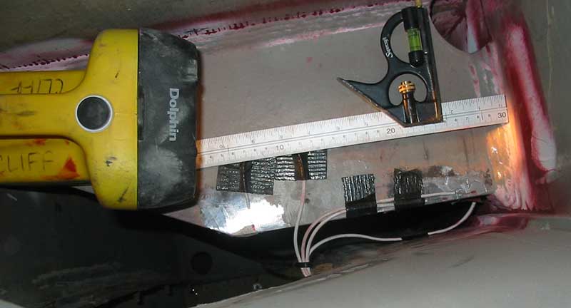
Figure 1 – Strain gauging of rotor poles
Strain gauging of rotor poles at Freeport most likely would have provided the correct material properties for the laminations in the rotor poles as stated in [1] but even with these properties, measured at Cadia, the designers struggled to get past the slenderness issue. The “wings” added to the Cadia rotor poles definitely were not deemed advisable after more FEA of the poles as stated in [1], at least by EAnD and the owner. This was a belt and braces addition by Siemens that we knew would not provide much benefit in terms of strength but the owner did not argue about their inclusion of the wings as they were not detrimental. Unfortunately, the wings were included in some motors ordered after the Cadia failure but this design has since been discontinued [11].
2.2.2 Legacy of the Cadia and Freeport motors
If looked at properly, the Cadia motor should be considered as one of the best designs of its type. Whilst it did have two problems, neither resulted in substantial downtime. The vibration issue was controlled by site maintenance and the vendor without any significant loss of availability until the strongback stiffener could be applied. The cracked rotor poles did not result in any damage to the windings again due to good maintenance. The motor was designed just outside the envelope of trouble free operation and the research undertaken to resolve the issues defined the envelope limit. Knowing these limits has benefited the entire mining industry. The overall system design including the foundations is one of the most cost-effective in the world. It would be of benefit to mine owners to study the designs of the Cadia and Freeport motors and their foundations before embarking on new projects. Foundations are now becoming too large and the stiffness targets for these foundations are excessive given that stator frames are now stiffer than the Freeport and Cadia designs. A lot of money is being wasted in concrete. The Cadia and Freeport foundations have stiffness levels of about 2 MN/m whereas newer installations are being designed with stiffness targets of 7 to 10 MN/m to support stators that are substantially stiffer than the Cadia and Freeport stators.
2.3 – Collahuasi hanger plate failures
The design of the hanger plates was looked at in depth during the failure analysis we performed for Collahuasi in 2006/7. Svalbonas’ statement in [1] that the failure of the hanger plates is not related to diameter is incorrect.
The failure of the Collahuasi motor was catastrophic and it occurred within months of commissioning. The Collahuasi motor was for a 40 ft SAG mill. The Antamina 38 ft SAG mill was also driven by an ABB motor and the hanger plates had not failed on that machine after several years of operation. Similarly, the Sossego motor for the 38 ft SAG mill had not failed. It too had an ABB motor and it had operated longer than the Collahuasi motor. Inspections of the Sossego motor indicated that the hanger plates had sharp corners in many of the hanger plates just as the Collahuasi motor had and that the magnetic pull per hanger plate is approximately the same as for the Collahuasi motor. Both motors driving the Telfer 36 ft SAG mill have hanger plates with sharp corners and had operated longer than the Collahuasi without failure. So why did the Collahuasi fail so quickly when the others did not?
Firstly, it is important to note that the failures at the corners of the hanger plates were not simply due to “stress concentrations” as stated in [1]. The re-entrant corners of the hanger plate cannot be analysed using stress concentration methods because both the design and manufactured corner radii were small. Below a certain value of corner radius, maximum stress adjacent to the corner radius does not increase. This is because the slot for the keybar in the hanger plate acts like a crack rather than a stress concentration. The hanger plates would have failed even if they had been made with the 3 mm radii called for in the design. So, the hanger plates in all the ABB ring motors were effectively “pre-cracked” prior to the motors being commissioned. Our recommendation to Alstom (the ring motor builder) to use a 10 mm radius for the hanger plates in the replacement Collahuasi stator was made to avoid the fracture mechanics regime in the hanger plate design.
Secondly, the diameter of the motor comes into play. The stiffness of the stator core is a function of diameter, thickness and depth. Stiffness is proportional to the cube of the core diameter, thus a small change in diameter can result in a large change in core stiffness. In smaller motors, the core can be self-supporting to a certain extent, i.e., it can act as a ring that does not transfer all of the electromagnetic loads to the frame. In fact, some of the vendor’s senior electrical engineers believed that the ring was completely self-supporting. Now, as the diameter of the motor increases, the global bending stiffness of the core decreases and more of the weight of the core and the electromagnetic forces in the air-gap are transferred to the frame of the motor through keybars and hanger plates. So, the Collahuasi motor failed much more quickly than other smaller motors primarily because of the diameter of the motor itself.
2.3.1 Lessons from Collahuasi
The Collahuasi motor resulted in extensive downtime for the plant and substantial losses. It is simple to point to the individual design faults in hanger plates, insulation, keybar retention and lamination failures for this motor and subsequent ABB motors as the cause of the failures but this is like not seeing the forest for the trees. The Collahuasi failure/s were cause by a lack of design oversight. This was specifically highlighted as a potential risk prior to the start of work on the project after an inspection/assessment of the ring motor factory. However, there is a strong desire in owners and even more so, in engineering companies, to not be involved in detailed design reviews for fear of attracting risk. We suspect that all the design reviews of all the mills and ring motors built since the Collahuasi motor was ordered would have cost less than the losses suffered at Collahuasi. Not reviewing the design just does not make sense. Even if a design review only has a slim chance of detecting a fault because of the complexity of the design issue, not performing a design review ensures there is no chance of finding it.
3 – Validation by Strain Gauging in Ring Motors and Mills
Svalbonas states that the failures in ring motors were not predicted by previous finite element analyses because insufficient strain gauging of motors had been undertaken on ring motors in the past. He contrasts this with the mills where strain gauging has been undertaken to validate design models. Reality is not so simple.
3.1 Design validation in ring motors
The strain gauging of the Cadia rotor poles (Fig. 1) was useful in providing an accurate estimate of the stiffness of the pole laminations. Lower the lamination stiffness resulted in higher the stresses in the welds. However, the data alone was not sufficient to avoid failures of some motors designed after the Cadia pole repairs were completed because the paradigm under which these motors were designed had not shifted to incorporate the lower lamination properties. This shift in understanding has now happened (see Section 4).
Strain gauging would not have been a benefit for the Collahuasi failures. It is unlikely that any measurement would have prevented the hanger plate failures.
A typical hanger plate in the ABB motor is shown in Figure 2(a) and a failed hanger plate is shown in Figure 2(b). It is clear from the geometry of the hanger plate, i.e., the sharp re-entrant corners, that the designers did not give much thought to fatigue and this is primarily due to the idea that the load in the hanger plates was not substantial. The success of smaller diameter machines would have reinforced this concept.
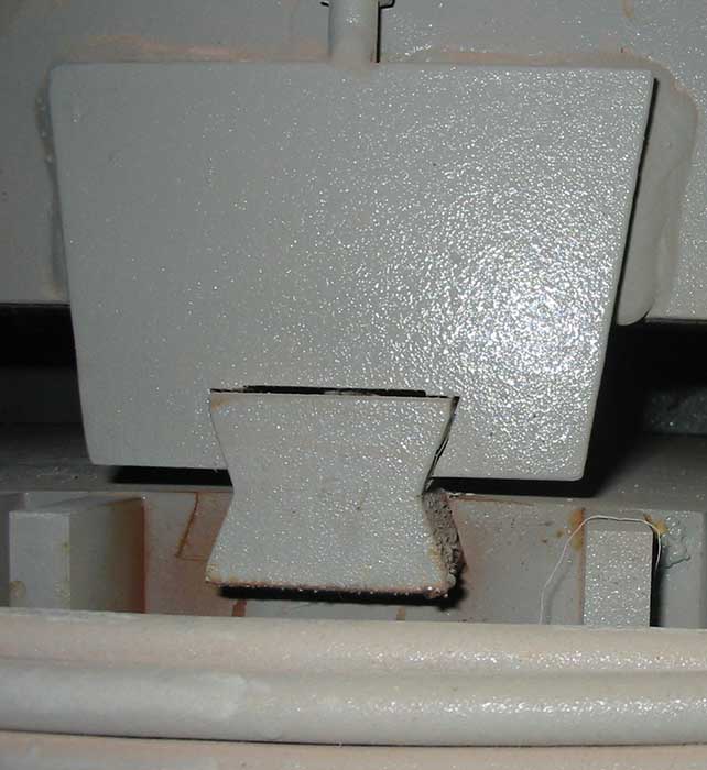
(a) Typical hanger plate
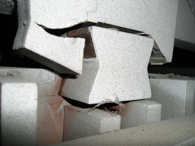 (b) Cracked hanger plate
Figure 2: Hanger plates in ABB motor
The strain gauging of hanger plates was undertaken by EAnD on the Collahuasi and other ABB motors as shown in Figure 3. Several complete keybar rows were gauged. It was not possible to measure the total load supported by a hanger plate as the load path from the core to the keybars to the hanger plate is not the same in all motor locations or conditions. At least 20% of the 500 plus hanger plates would need to be gauged to get a reasonable estimate of the load transfer between the core and the frame. This is because there is a substantial hysteresis in the load in each hanger plate during a full load cycle. The complexity of the motor precludes simple measurement techniques being used such as strain gauging to validate a design directly. Real safety factors cannot be determined by measurement as claimed in [1]. The design process for the ABB motors is by necessity evolutionary, not deterministic. What happened at Collahuasi was that the size of the motor extended well beyond the regime in which smaller motors operated. The loads in the hanger plates became substantial and thus a change in design was needed. Such a change in regime may be detected in design through analysis and reviews but it cannot be detected by instrumenting smaller machines as they do not operate in the new regime.
Figure 3: Strain gauging of hanger plates
An in-house or external, detailed design review by a good designer who was not immersed in actually doing the design most likely would have detected the problems in the Cadia rotor poles. There is no guarantee that the problem with the hanger plates in the Collahuasi hanger plates would be detected by such a review as it requires a paradigm shift but there was a possibility nevertheless.
3.2 Design validation in mills
Svalbonas says in [1] that ring motor designers must validate their designs against strain gauge measurements just as he has done in mills. Whilst he mentions the difference in loading between mills and ring motors, he fails to consider the effects of the much greater complexity in construction of ring motors in his comments. The stresses in the rotating element of a mill can be characterised with a relatively simple strain gauge measurement programme. It would require of the order of 12 gauge sets. The complete characterisation of a ring motor requires strain gauging of rotor poles (about 8 gauge sets); strain gauging of the various stator components (keybars, supporting plates and frame – 20 to 30 gauge sets), vibration measurements requiring about 30 channels, modal measurements for in-plane and out-of-plane modes, temperature measurements, flow measurements and determination of the foundation stiffness using a further 8 vibration channels. Whilst validation should be performed by the ring motor vendor, the task is much more complicated than applying a few gauge sets to measure some local stresses.
It would be unreasonable to dismiss the viewpoint of a mill designer on the design of ring motors just because the mill structure is relatively much simpler than the motor. So, let us look at the design validation of mills. Svalbonas [2] presents strain gauge measurements from a mill in a paper dated 1979. This data was used to assess the accuracy of a finite element model of the mill. The measured stresses in a particular direction are calculated in [2] by multiplying the strain in that direction by the elastic modulus. This is incorrect as a biaxial stress state exists in the mill and the stresses are a function of both the radial and circumferential strains. This error could be ignored if it were an isolated on but it is not. We have found the same error in strain gauge measurements of larger mills taken more recently. There is not much point validating design models against erroneous measurement data.
There is a bias in engineering that analysis is always doubted in the face of conflicting measurement data and this is evident in the interpretation of stress measurements in [9]. Stresses were measured at the weld toes of the can-to-can flanges in the Telfer ball mills by EAnD. These stresses were substantially lower than the calculated stresses. Svalbonas in [9] claims that it is “known fact” that a “standard” finite element analysis results in over-estimation of stresses at this location. This claim is wrong as shown by analysis in [10] and by measurement on the Antamina mills. The measured stress ranges at the toes of the welds at the can-to-can flange in the Antamina ball mills were slightly higher than those obtained from the “standard” finite element analysis that was undertaken during the design of the mill. The difference between the measured stresses at Telfer and Antamina is that the liners in the Telfer ball mill had been wedged by ball scats and ore as shown in Figure 4 and thus the liners supported part of the load [10]. What this means to an owner is this. If the owner accepts higher than allowable stresses at these joints on the basis of the erroneous “known fact” that FEA over-predicts actual stresses, the owner will accepting a mill design that relies partly on the liners for its structural integrity.
In future posts, we will present other design and design validation issues in mills. However, the two examples above are sufficient to indicate that the state-of-the-art of design in mills is not substantially any different from than the state-of-the-art of design in ring motors. There are still gaps in knowledge bases of the mill designers.
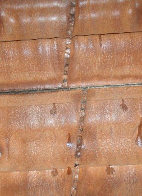 Figure 4: Packing (wedging) of liners enabling axial load transfer
4 – Ring Motor Repairs
The design changes made to both Siemens and ABB ring motors after the Cadia and Collahuasi failures were more involved than the stiffening of the pole ribs and the increase of the hanger plate radii discussed in [1]. Again, this is due to the evolutionary design of these machines.
At the time that the Cadia rotor poles failed, the Siemens motor design had already gone through an evolutionary design change that resulted in stiffening of the stator frame [6, 7]. The rotor pole failures too required an evolution. The description of the repairs to the Cadia poles by Svalbonas in [1] is not accurate. The “wings” that were added to the poles were not “deemed advisable” by EAnD and the owner as explained in Section 2.1 above as they did not improve the strength of the welded joints in the ribs. In subsequent motors, the wing design was used in Siemens motors except in cases where the motor was specified by EAnD. We required that the rotor pole design be modified to eliminate the wings and to add two more rib sets to the pole resulting in one pair of ribs per pole. This design was implemented at Antamina, RPM (Brazil) and Sino Iron. Siemens have now adopted the four-pair rib design for all their new motors [11].
The changes made to the ABB hanger plates were part of a wide range of changes made to the design since 2006. These changes address the failure at Collahuasi and other issues in the older machines through changes in insulation, lamination fixing and core expansion. It will be some time before the effectiveness of these changes can be determined.
CONCLUSIONS
The failures of the rotor poles at Cadia and at other plants and the failure of the core support system at Collahuasi were not simply due to a lack of measurements on preceding ring motors as stated in [1]. Ring motor design is an evolution and at some critical size, the motors started to behave differently from earlier, smaller motors. As the motor diameters increased, the stator cores shed more load to the supporting structures. There would be little point in measuring the loads in a hanger plate in a smaller motor built in the past if that hanger plate does not support any substantial load. Also, because of the load hysteresis, strain gauging of just a few hanger plates would not provide an accurate estimate of the applied loads.
Svalbonas’ paper portrays ring motor design and validation as being well behind the state-of-the-art in mills yet Svalbonas has had no involvement in ring motor design or in the analysis of any of the failures described in [1]. The recent spate of mill failures; errors in strain gauge data from mills; a general reticence by mill designers to investigate the discrepancies between measurement and analysis; and a wide divergence between the mill vendors in how they assess their designs and manufactured components does not support Svalbonas’ conclusion that mill designers have advanced further than ring motor vendors in determining the safety factor in their product.
The root causes of the failures at Collahuasi and Cadia were (a) faults in the vendors’ design culture and (b) indirectly to motor diameter. Similar problems exist in the design cultures of mill manufacturers, as the absence of failures in the early 2000s has bred an air of complacency. Unfortunately for all, this good run of mill operation without failures appears to have ended.
One thing that strain gauging and vibration testing of the Siemens and ABB ring motors has confirmed is that the designs are completely different both electrically and structurally. This is poorly understood in the mining industry.
References:
[1] Svalbonas, V., 2008. Gearless motor failures – a mill designer’s viewpoint. MAPLA Conference, Chile.
[2] Svalbonas, V., 1979. Some considerations in computer structural analysis of large grinding mills. SME Annual Meeting, New Orleans, Louisiana.
[3] Yánez, G., Tapia, H., 2008. Reparacion de fisura de shell y giro de tapa de descarga del molino sag 36’x 15’ de minera candelaria. MAPLA Conference, Chile.
[5] Meimaris, C. and Lai, W. K. K. L., On the comparison between measured and calculated stresses in large SAG mills. Minerals Engineering 24 (2011)
[4] Meimaris, C., Lai, B., Price, B. F., Manchanda, S., 2006. How big is big? – revisited. In Proceedings of the SAG 2006 Conference, Vancouver.
[5] Meimaris, C. Higher Doctorate Dissertation, 2011
[6] Kummlee, H., Mienke, P., 2001. A mechatronic solution – Design and experience with large gearless mill drives. In Proceedings of the SAG 2001 Conference, Vancouver, Canada.
[7] Meimaris, C., Lai, W. K. K. L., Cox, L., 2001. Remedial design of the world’s largest SAG mill gearless drive. In Proceedings of the SAG 2001 Conference, Vancouver, Canada.
[8] Frank, W-D., Gearless drives – Experiences and new/future developments. In Proceedings of the SAG 1996 Conference, Vancouver, Canada.
[9] Orser, T., Svalbonas V., Van de Vijfeijken, M., 2011. Conga: the world’s first 42 foot diameter 28 mw gearless sag mill. In Proceedings of the SAG 2011 Conference, Vancouver, Canada.
[10] Meimaris, C. and Lai, W. K. K. L., Fatigue design of mills. Minerals Engineering, 30 (2012).
[11] Recent discussions with Siemens.