Grinding Mill Foundations
Most of our work since 2000 has been in developing grinding mill foundations to avoid vibration and unacceptable deflections. On a recent project for a plant in Peru, the client was told by the mill vendor that there was no need to do a systems (dynamic) analysis on the mill foundations because the mills on that project were gear driven rather than being driven by ring motors (gearless drives). This shows a complete misunderstanding by mill vendors, or rather this particular mill vendor, about how mill foundations behave.
1 – Past Failures and Difficulties:
The most notable failures and difficulties in mill foundations have been caused by gear drives. Some examples we have worked on are:
Mt Leyshon
The three foundations at Mt Leyshon all failed within a short time. The failures were catastrophic, i.e., the cracks in the piers completely failed and there was no way that the mills could be operated. In c. 1992, one of our staff was asked to determine why these foundations failed and to model a proposed fix. The failure was traced to the gear forces as these matched one of the natural frequencies of the foundation piers. Each mill was down for nearly a month while the repair was made and the concrete allowed to cure.
North Parkes
The next foundation we worked on was at North Parkes. There, the foundations on the original plant would transient manner. We were asked to design the foundation for the new plant from the point of view of vibration. A block between the mill bearing piers was required to avoid vibration that would have occurred due to the combination of raft dimension, mill frequencies and soil properties. There were no issues with vibration on these new foundations. This work then led on to the Cadia project and many others (thanks to Geoff Cullen and Alan Boughey).
Fimiston (KCGM)
Another interesting foundation we studied is the Fimiston SAG mill foundation. The gears on the mill on this foundation were very difficult to align and the alignment and vibration of the system was worse when the mill was rotated in one direction rather than the other. We found that the direction of rotation would result in a change in the vibration levels at the pinion piers of up to 7 times depending on the level of damping in the structure (from 5 mm/s to 35 mm/s). This was the first analysis that explained why the direction of mill rotation affected on vibration levels.
 Fimiston mill foundations –
Mill and soil not shown for clarity
Red Dog Mine
One of the more interesting projects that we have been involved with was the Red Dog Mine SAG mill foundations. The mills are supported on steel supports rather than concrete. The mills operated for many years without issue and then began to vibrate excessively. A consultant/mill-designer investigated the problem and recommended substantial stiffening to the steelwork apparently to overcome “softening” of the steelwork due to long-term deterioration. We thought that it was odd that the supports would suddenly start to vibrate and recommended that the pinions be changed out. This solved the problem and saved the owner a lot of money. So again, gears and pinions were the main cause of vibration.
Gearless Mill Drive Foundations:
We have never encountered a foundation vibration problem with operating gearless driven mills, although there may be examples of this about. The main problems with gearless driven mills is stiffness and strength; there are several examples of cracked foundations at the supports for ring motors.
We have stated in a previous post that the stiffness of ring motors and therefore the resonant frequency of the stator is dependent on the stiffness of the foundation supports; see: http://www.eand.com.au/?p=168. Inclusion of some small details in a foundation of standard configuration (mill and motor piers connected) can produce a change in the natural frequency of the motor of about 5% and this is always worth doing as it does not result in a significant cost. Once the piers have been sized and the details developed so the motor does not vibrate, then the system assessment reduces to ensuring that the foundation does not vibrate due to mill forces, i.e., avoiding global vibration including the soil-structure interaction. This is the same task encountered when designing a gear driven mill foundation once the gear forces have been managed.
In terms of actual vibration problems with ring motors, we know of the Cadia vibration issues only. There, we proved conclusively that the vibrations were not related to the design of the foundations.
2 – Difference between Geared and Gearless Mill Foundation Design
There is a key difference in system analysis of geared and gearless mill foundations.
- In gearless motor foundations, one of the main tasks is to ensure that the foundation prevents the motor from deflecting or vibrating excessively. If this is done properly, then the motor and the motor piers will effectively behave as static structures. The remainder of the design analysis then involves the assessment of the other dynamic forces, primarily from the mill.
- In gear driven mills, there will always be vibration from the drive and the mill. This cannot be eliminated. The aim of the analysis is to ensure that (a) the foundation does not resonate or (b) that there is enough stiffness and damping in the foundation and the sub-surface soil/rock to ensure that the vibration does not result in failure if resonant frequencies cannot be avoided.
So, for one mill type, the system analysis is mostly about making sure the equipment (the ring motor) will not vibrate or deflect whereas for the other, the primary task is to make sure the foundations will not vibrate.
3 – How to Design a Mill Foundation
The steps are:
- Understand the loads – thermal, accident (short-circuit), gear loads, mill loads, liner frequencies. You will need to do some measurements to get these loads;
- Get the soil properties – Note that the soil properties will be approximate and you will need to perform a sensitivity analysis for the soil properties. The extent of the soil/rock model under the foundations should be an order of magnitude greater than the foundation characteristic dimension in each of three directions;
- For gearless drives, get the motor vendor not the mill vendor to define the required stiffness for their motor to behave properly;
- Create a model that includes the mill, ring motor, pinions, gears, concrete and soil as necessary;
- Assess the critical performance parameters, viz., deflection of motor and piers; vibration levels; hold-down forces, motor behaviour, etc., for all conditions;
- Then, Bob’s your uncle and you are done.
None of the “answers” you get will be “right” because you won’t know the forces to within 10 or 20% and you certainly have no way of being sure the soil properties are right. So, it will almost always be necessary to iterate to get the “right” design. The foundations may vibrate under certain soil property combinations and this will require some changes by the concrete designers. The ring motor may overload the hold-down bolts under accident conditions needing changes to bolt materials or increases in size. In the mid-2000s, it was sometimes necessary to increase the stiffness for ring motor pier connections to avoid stator vibration due to very soft soils. This is less likely to be a problem now but the possibility should always be assessed. If motor diameters increase or power draws increase, the present design of stator frames may well require modification as a result of these system investigations.
There is no point just doing a modal analysis for gearless or gearless drives. These would not have detected any of the GMD issues at Antamina, Collahuasi, Cadia or Freeport. A modal analysis is just the first step in the overall dynamic assessment. Separating the forcing and resonant frequencies by X% will not be good enough as there are too many frequencies to separate.
The length of the foundations is very important in determining behaviour. This means that SAG mill foundations behave very differently from ball mill foundations.
4 – Mill Designer Stiffness Criteria
One of the mill designers performs a calculation to determine the “target stiffness” of the foundations given the mill and ring motor stiffnesses. We have noticed that this ends up at about 10 MN/mm for large drives. We have pointed in another post that the Freeport 38 ft installation has a stiffness of about 1.2 MN/mm and the Cadia 40 ft stator has a stiffness of about 2 MN/mm. It is evident that 10 MN/mm is overkill.
5 – Mill Vendors being Difficult
We find that some US mill vendors will not provide drawings to enable the inclusion of the mill and bearings in a system model. They complain about proprietary information and the danger of the loss of their intellectual property. We are constantly amazed by this argument and it is up to the Owner to overcome this so that the system design can be completed in a reasonable time-frame. All that is required is enough information to model the overall dimensions of the mill; mill component weights and stiffnesses; liner details; gear dimensions, PCDs, pressure and helix angles; bearing housing details; and bearing stiffnesses. In other words, what is needed is a set of engineering drawings with dimensions and no tolerances. The secret IP of a good mill design is in the detail and tolerancing, not the overall dimensions, so the only thing that withholding this does is delay the project and increase risk.
.
6 – Some Myths
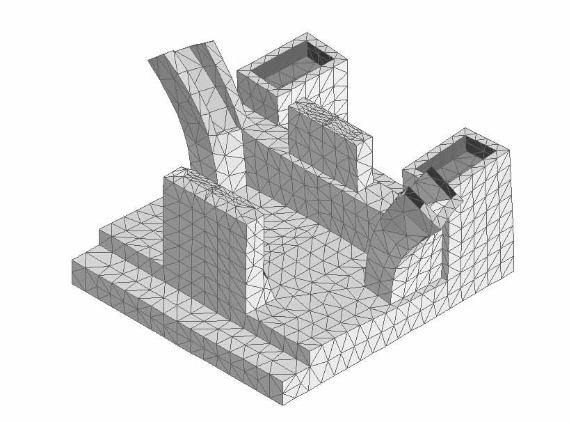
- Multiple mills on a single foundation cannot be modelled (from a mill vendor’s design consultants). Wrong. We have modelled Lumwana, Boddington and others successfully (see example of a multiple mill model below).
- The soil is not important and the foundation model can be fixed under its base for analysis. Again wrong. The El Teniente SAG mill foundations had to be stiffened as did the stator frame to ensure there would be no vibration because the soil properties were very poor.
- Foundations cannot be built on piles. Wrong again. There are successful examples of piled mill foundations.
- The mill vendor should be responsible for the system analysis. Wrong. A mill vendor is experienced in mill design and generally knows nothing about ring motors or foundations.
- A geared mill does not require a torsional analysis. Wrong for several reasons but for this post, the torsional harmonics can be greater than the dynamic loads of tooth mesh, mill and pinion rotation and liner loads.
- Modal analysis is sufficient for assessment of mill systems. Not so. There are many mill systems that operate at resonance. There are too many forcing frequencies to consider in order to avoid resonance. Furthermore, the vibration of a ring motor is not resonant. It is sub-harmonic. Modal analysis is not sufficient.
- Motor vendors understand the hold-down forces. This is not universally correct. On vendor does not use a dynamic analysis to determine peak hold-down forces during a short circuit whereas the other does. The one that doesn’t is wrong.
Multiple mill foundation.  Soil not shown for clarity.
SUMMARY
Most of the major problems related to foundation design are from gear driven mills, not gearless mills. System analyses are useful for both types of mill.
The main aim of a system stiffness analysis is different for geared and gearless mills. In the former, the aim is to stop excessive vibration in the foundations; in the latter, it is to make sure that the ring motor acts as a static structure.
Mill design consultants produce stiffness targets that are too conservative. The Cadia and Freeport foundations are excellent examples of what can be done without going to 3 and 4 m wide motor piers.